You’ll disconnect your negative battery terminal, access the factory brake controller connector beneath your dash, and match your truck’s year to the correct OEM part number. Install the bracket using push pins, then route the blue wire to your passenger-side foot well for brake output, connect the red wire to fuse F71 or F72 for power, and ground the white wire to your vehicle’s ground circuit. Test functionality with AlfaOBD software before towing. There’s much more to explore about optimizing your brake controller’s performance.
Identify Your Ram 1500 Year and Check Controller Compatibility
Before you install a trailer brake controller on your Ram 1500, you’ll need to pinpoint your truck’s year and verify compatibility with available options. Check your VIN or door sticker to confirm whether you own a 2013-2018 model, 2019-2024 DT series, or Ram 1500 Classic variant. Each generation requires different OEM part numbers and installation procedures. For 2019-2024 DT models, you’ll need the trailer brake control module kit and security bypass harness. Locate the specific controller part number matching your year group. Consider battery disconnection alternatives if you’re uncomfortable disconnecting power directly. Cross-reference Curt Custom Wiring Adapter compatibility for recent models. Understanding your truck’s weight capacity and payload needs will help ensure your trailer brake controller is appropriately sized for your towing requirements. When selecting a controller, review the towing capacity specifications to match your specific hauling applications. The total installation time for this project typically takes around 45 minutes once you have all components ready. Testing with AlfaOBD software after identifying your truck guarantees proper functionality before full installation.
Disconnect the Battery and Prepare Your Workspace
To prevent electrical damage and guarantee safe installation, you’ll disconnect the negative battery terminal using a 10mm wrench on the terminal stud. This step prevents unwanted check engine lights or diagnostic codes during electrical work.
Next, remove the center stack dash piece by unbolting two screws at its top, then pull it straight toward the cab’s rear. Disconnect all plugs on the console’s back for easier handling.
Access the trim panel under the steering wheel by removing two 7mm screws at its bottom. Pry the panel’s top edge to release clips, carefully detaching the hood release latch and data link connector. When routing wires during installation, ensure you avoid damaging vehicle electronics behind the dash by taking care during any drilling or fastener work. Proper wire management is essential, especially when working near sensitive electrical components that control frame modifications and other critical truck systems. Always consult manufacturer specifications for torque specifications to ensure all fasteners are secured correctly during reassembly.
After completing your installation, snap the panel back and secure it with the two bottom fasteners. Follow the battery reconnection procedure once all wiring and installations are complete for proper dash panel reassembly tips.
Locate and Access the Factory Wiring Harness Under Your Dash
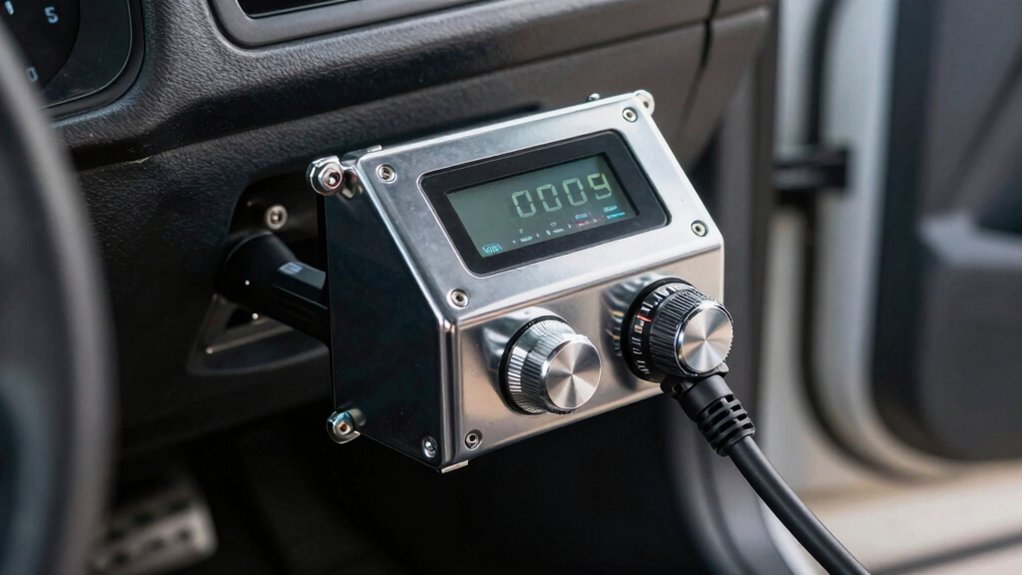
You’ll find the factory brake controller connector somewhere beneath your dash, though its exact location varies by model year and trim level. Start by accessing dashboard trim components to expose the wiring area. Look above the gas pedal or behind the center dash, depending on your configuration. The correct connector typically features a dual green wire setup and distinct pin configurations that match brake controller requirements.
Once you’ve located potential plugs, compare pin counts and wire colors against your installation documentation. Multiple connectors exist in this area, so systematic identification prevents mistakes. Reference manufacturer diagrams showing exact connector positions for your model year. Remove necessary trim panels carefully to avoid damage while routing harness through dashboard pathways. To maintain a clean installation, use zip ties to secure the harness and keep it away from hot or moving parts. Professional installation videos provide valuable visual confirmation of the correct connector before proceeding. Testing each pin with a multimeter ensures proper voltage and continuity before final connection. For vehicles without factory harnesses, aftermarket solutions may be necessary to establish proper brake controller connectivity. Proper stopping power performance depends on correctly identifying and connecting to the factory wiring harness without shortcuts or cross-connections.
Install the Bracket and Mount the Controller Module Securely
With the factory wiring harness located, you’re ready to secure the bracket and controller module in place. Begin by inserting three push pins into the bracket’s square holes for secure hardware installation. Align the Phillips head screws with the dash’s designated mounting holes, then tighten them firmly. Use seven millimeter screws on panel sides if necessary for additional stability.
Next, perform precise bracket positioning by pressing it into place and ensuring it sits flush against the dash. Position the bracket so the controller module’s hooks align with the far left positions. Slide the module top into these hooks first, then press the bottom to clip it securely. Verify the fit with a gentle tug test. The bracket provides mounting location for the trailer brake module, keeping it out of sight beneath the dashboard. For those preferring professional installation, specialized installers abound across North America to ensure safe and reliable hitch system setup. U-Haul operates over 1,500 locations throughout North America where certified technicians can handle trailer brake controller installations with expertise and efficiency. Ensure all bolts are tightened to manufacturer specifications for a secure connection. Finally, reinstall your knee bolster with two bottom screws to complete the installation.
Connect the Blue, Red, White, and Striped Wires Correctly
Four critical wires—blue, red, white, and striped—must be connected correctly to establish proper brake controller function. The blue wire routes to your passenger-side foot well as the brake output signal, using 12 AWG wire gauge for adequate capacity. Connect your red wire to the positive battery terminal at fuse F71 or F72, ensuring you check jumper wire amperage doesn’t exceed 30 AMP maximum. The white wire grounds to your vehicle’s identified ground circuit, completing the electrical return path. Proper grounding is essential to avoid intermittent braking or voltage issues that can compromise trailer brake performance. Rather than relying on the ball connection for ground continuity, ensure your ground wire is securely attached to the vehicle frame with appropriate gauge wiring to handle the full electrical load. After making these connections, you’ll need to enable the tow package in your vehicle’s ECU using an OBD2 adapter and compatible app to activate the integrated trailer brake module functionality. Inspect connector security at both the 4-way and 2-way gray connectors after making connections. Verify all wire isolations prevent short circuits, then confirm continuity before reassembling trim components.
Program Your Controller Using the OBD2 Connection
Once you’ve verified your wire connections, you’re ready to configure the controller through your Ram 1500‘s onboard diagnostic system. Start by installing the FCA Security Gateway Bypass Module into your OBD port, then position your vehicle in run mode without cranking the engine. Install the Vlinker MC+ Bluetooth module, which offers superior Bluetooth module compatibility for your diagnostic needs. Open the AlfaOBD app on your Android device and pair it using code 1234. Select your Ram 1500 model year, then access the Body Control Module. Navigate to Car Configuration Change and enable the Integrated Trailer Brake Controller option. Complete the OBD2 programming procedure by finalizing the PT Chassis Net module settings. Proper adjustment of gain, sensitivity, and maximum output settings ensures your trailer brakes apply proportionally with your vehicle’s braking force for smooth and safe stopping. Testing your controller settings at moderate speeds on open roads will help you avoid wheel lock-up and verify sufficient stopping power. For added convenience and portability across multiple tow vehicles, consider wireless alternatives like the Curt Echo that offer Bluetooth connectivity without requiring OBD2 programming. Note that 20% of 2017 models may require the security bypass cable depending on your vehicle’s security implementation. Your trailer brake service light will illuminate, confirming successful activation.
Confirm Programming Success Before Moving Forward
After finalizing your PT Chassis Net module settings, you’ll want to verify that your Ram 1500’s ECU has recognized and integrated the trailer brake controller before taking your truck on the road. Check your instrument cluster menu—the trailer brake option should appear post-installation. Scroll through cluster settings to locate it. Next, confirm the infotainment system displays the trailer brake interface. Manually engage brakes using the console button and feel them activate without vehicle motion. Test the controller slider; screen response should occur immediately. Review your OBD programmer for a green light indicating successful completion. A proportional braking system provides smooth trailer deceleration that responds immediately without jerking, adapting to various terrain conditions for enhanced towing safety. Consider upgrading to a proportional brake controller for smoother, more terrain-adaptive braking performance during your towing operations. Trusted brands like Tekonsha, Redarc, and Curt offer digital diagnostics that simplify verification of successful integration. If you don’t see these confirmations, troubleshoot programming errors by checking for existing fault codes that could’ve bricked your ECU. You may need to use AlphaOBD software or a wireless OBD scanner to communicate with the truck’s ECM and resolve any module recognition issues. Verify project completion has no check engine lights before reconnecting the battery ground.
Mount the Switch on Your Instrument Panel
Before you mount the switch on your instrument panel, disconnect the negative battery terminal using a 10mm wrench to prevent electrical shorts. Remove the center stack by extracting the two top screws and pulling straight out.
Position your switch where you’ll access it easily while driving, ensuring it doesn’t obstruct your road view or interfere with existing controls. Locate the mounting holes on the right-hand side of the dash beneath the steering column. These existing square holes accept 7mm screws for bracket alignment.
Install the bracket using your provided hardware kit, securing it firmly with self-tapping screws. Avoid overtightening to prevent stripping. Be mindful of what is behind the dash when drilling to avoid damaging vehicle electronics. Gather essential tools like a socket set and torque wrench before beginning installation to ensure you have everything needed for proper mounting. Snap the controller module into the bracket’s far left hooks and press down. This placement balances switch accessibility with dash aesthetics, maintaining your vehicle’s interior appearance while providing convenient trailer brake control.
Connect Your Controller to the Touchscreen System
To guarantee your trailer brake controller functions properly with your Ram 1500’s infotainment system, you’ll first need to verify compatibility with your truck’s equipment. Connect the controller’s harness directly to your truck’s towing electronics using the included plug-and-play connector. This integration confirms seamless operation between your controller and the Uconnect 5 touchscreen.
After establishing the physical connection, activate the feature through your BCM programming using the OBD Genie C-TBC programmer. Flash your Uconnect software to add the trailer brake controller functionality to your display. Once activated, the controller appears on your 8.4″ or 12″ touchscreen, providing convenient accessibility to brake adjustments. Note that the 82219240AB module is specifically designed for 2025-2026 Ram 1500 trucks with these screen sizes and requires dealer programming to add the necessary sales code.
You’ll now customize brake force output and gain settings directly through the touchscreen interface, enabling proportional braking response tailored to your trailer’s load requirements.
Test Brake Response and Verify Safe Operation Before Towing
You’ll need to run several diagnostic tests before towing to confirm your Ram 1500’s trailer brake controller operates safely and reliably. Start by disconnecting your trailer and setting the controller to maximum power and boost. Use a circuit tester on the brake output contacts to isolate controller performance. Have a helper activate the manual override lever while you probe the blue brake wire for voltage—no signal indicates internal damage requiring replacement.
Next, reconnect your trailer with functional brakes. Engine running, apply your brake pedal and observe the controller display for signal output. Feel the trailer brakes engage during driving. Finally, troubleshoot error codes like OL indicating shorts, and evaluate wiring integrity by testing supply and ground connections. Verify no constant output occurs without brake input, confirming safe towing operation. Check that the white wire ground connection is secure at both the controller and trailer plug, as improper grounding causes most operational failures.