You’ll systematically test your trailer brake controller through bench testing, resistance measurements, and road calibration. Start by gathering a multimeter, test light, and power source, then verify all connections and inspect wiring plugs. Bench test using a 1156 bulb to observe voltage output proportional to brake pressure. Test magnet resistance—individual magnets should read 3.0–4.0 ohms. Activate the manual override to confirm functionality, then dial in gain settings at safe road speeds on dry surfaces. These foundational steps reveal operational issues and prepare you for deeper diagnostics.
Gather Tools and Verify Connections
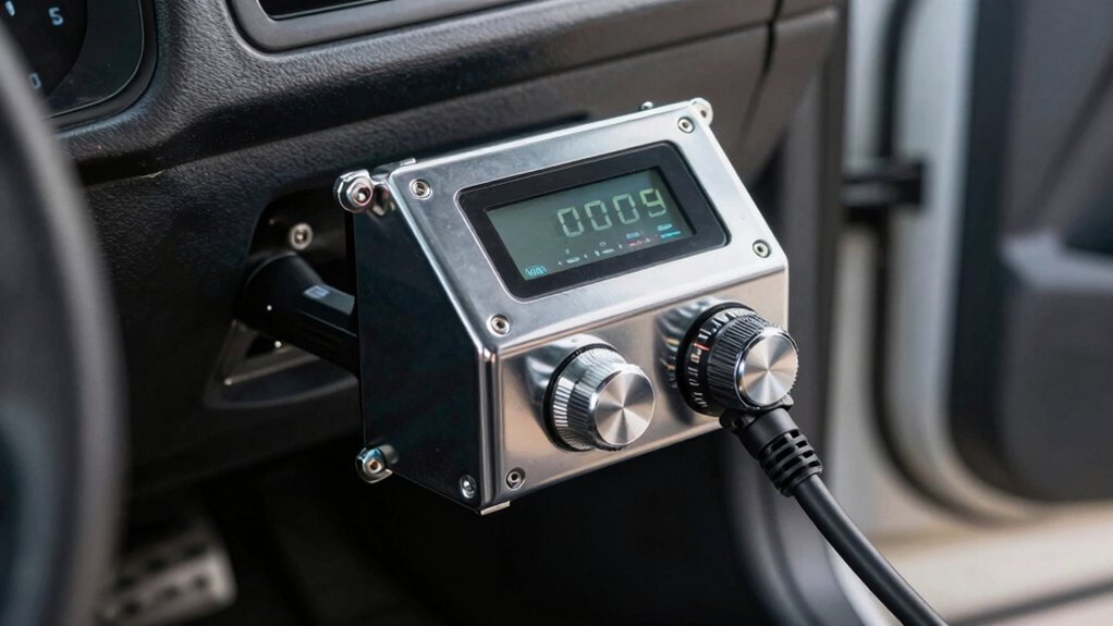
Before you dive into testing your trailer brake controller, you’ll need to gather the proper tools and verify all connections are in working order. Assemble a digital multimeter, test light with 12V filament bulb, and a 12-24Vdc power source capable of 8-16A. You’ll also need basic wiring tools and an Electric Brake Force Meter with a 25-ft cable for in-cab testing. The 25-ft cable allows for easy, one-person testing from inside your vehicle without requiring a trailer.
Next, thoroughly inspect vehicle circuits by checking the truck-side brake controller output and examining tail lights, turn signals, and 12V+ reverse circuits. Confirm the orange power wire receives voltage. Guarantee proper grounding connections by verifying the trailer frame or axle provides solid ground contact. For optimal results, consider using color matching techniques when verifying wire connections to ensure correct polarity throughout the system. A properly functioning brake controller ensures that braking force is proportionally applied to the trailer, preventing unsafe stopping distances and excessive wear. Inspect the brake controller wiring plug for any visible damage before proceeding. Verify all connections display “C” for connected status to ensure the system is ready for testing.
Bench Test Your Brake Controller With a 1156 Bulb
How do you verify your brake controller’s core functionality without connecting it to a vehicle? You’ll bench test it using a 1156 bulb to guarantee trailer brake loads safely.
Wire the bulb to the controller’s blue output wire, grounding it to the negative battery terminal. Connect your power supply: black wire to positive, white wire to ground. Adjust the manual brake pressure control and observe the bulb’s brightness increase proportionally to your output voltage validation on the display.
Next, simulate brake signals by connecting the red wire to your 12V source. The output should ramp to maximum smoothly. Use the sync lever to control ramp speed. The sink lever controls how quickly the brakes apply to the maximum pressure level set on your control unit. Monitor controller temperature monitoring throughout testing to validate safe operation. Proportional controllers deliver superior smoothness compared to time-delayed models, making them ideal for validating braking performance during bench testing. When testing, ensure your controller compatibility matches your specific trailer’s braking system requirements. Different trailer types may require different controller configurations depending on whether your trailer uses electric brakes or another braking system. Disconnect the red wire to confirm zero output without input.
Test Brake Magnet Resistance With a Multimeter
Once you’ve verified your controller’s basic function, you’ll need to test the brake magnet resistance to guarantee your trailer’s braking system operates reliably. Set your digital multimeter to the Ohms (Ω) setting, then place the black probe on one magnet wire and the red probe on the other—polarity doesn’t matter here. Secure your connections firmly before taking readings. Individual magnets should measure 3.0–4.0 ohms depending on brake size. Resistance variations outside this range indicate coil condition testing failures. For parallel circuits with four magnets, expect approximately 1.0–1.1 ohms total. Lower readings suggest shorted windings; higher readings point to open coils. Test each magnet individually to isolate problems, then replace any magnet reading outside specifications. Remember that resistance readings increase when brakes are warm or hot, so take measurements only when brakes are cold for accurate results. Proper adjustment of your brake controller gain settings will complement these resistance tests to ensure balanced braking performance between your tow vehicle and trailer.
Test Manual Override and Gain Control
After confirming your brake magnets function within specification, you’re ready to evaluate the manual override and gain control systems that allow independent brake application. Start by setting the gain dial to minimum, then activate the override button with a quick double-click. You’ll observe the test light illuminate and hear an audible hum from the trailer brakes. Jack up the trailer axle and spin a wheel while engaging override—the tire should lock immediately. If the wheel spins freely, adjust gain settings incrementally upward until achieving resistance just below lock-up. If you troubleshoot override malfunction by finding no test light response, check the blue brake output wire for continuity using a circuit tester to diagnose controller failure. Connect a 5 to 21 watt filament globe between the earth pin and trailer brake pin to verify proper electrical circuit operation during your testing procedure. The Tekonsha Primus IQ and other leading aftermarket controllers feature adjustable brake boost levels that enhance smooth, reliable trailer braking performance. For those seeking wireless alternatives, Bluetooth-enabled controllers like the Curt Echo offer modern convenience with smartphone app control during testing and operation. Understanding brake controller compatibility with your specific vehicle and trailer combination ensures optimal synchronization between towing vehicle braking and trailer braking systems.
Dial In Gain at Safe Road Speeds
Now that you’ve confirmed proper brake magnet function and manual override response, you’re ready to dial in gain settings during controlled road testing. Begin testing at 20-25 mph on flat, dry road surfaces to establish baseline gain settings. Start with manufacturer-recommended values (typically 3.0-4.0 for empty trailers), adjusting based on load weight and trailer type. Monitor trailer engagement—it should occur just before or simultaneously with tow vehicle braking. If the trailer lags, increase gain; if it locks up, decrease it. Make gradual adjustments in small increments and retest at consistent speeds. Document all changes. Gain represents the amount of braking power sent to the trailer and must be carefully calibrated to achieve proper braking balance between your vehicle and trailer. Remember that proportional controllers provide smoother stops and more efficient braking compared to time-delay systems, especially when managing hill descents. For heavier loads and frequent towing situations, proportional controllers offer superior safety through their use of internal accelerometers or pendulum sensors to detect deceleration rates. Ensure all power connections use 12-14 gauge stranded wire minimum to maintain reliable signal transmission during testing. Once comfortable with baseline settings, configure load sensing settings and emergency mode adjustments before progressing to variable speed testing.
Still Having Issues? Run These Diagnostic Checks
When your trailer brake controller isn’t responding as expected, systematic troubleshooting will pinpoint the root cause before you invest time in unnecessary adjustments. Start by checking status of controller light indicators on the remote head at base pin 5—green or flashing blue signals proper calibration. Next, verify resistance of wiring harness using your multimeter, measuring 12–14 volts at the 7-way brake pin during manual override. Less than 11 volts indicates weak connections or undersized wire. Wiggle the harness to reveal intermittent breaks or chafing. Inspect brake magnets for resistance readings: 10-inch drums should read 3.0–3.8 ohms; 12-inch reads 2.2–2.8 ohms. Compare wheels for spreads exceeding 0.5 ohms, which cause uneven braking. Test trailer ground continuity for zero readings, isolating wires individually to confirm proper connections. Clean any corroded pins on the connector to ensure proper electrical contact. If resistance testing reveals readings outside the expected range, disconnect brake hubs one at a time to isolate whether the fault originates in the drawbar or chassis wiring. Electric brake controllers provide faster response times compared to hydraulic systems, which can help you identify performance issues more accurately during diagnostic testing. Proper brake system function is essential for the weight distribution that central hitch mounting provides, ensuring safe towing performance throughout your journey.
Test Amperage Draw and Current Flow
Amperage measurements reveal whether your brake magnets are drawing the correct current from the controller’s DC output. You’ll need to set your multimeter to DC amps mode and place it in series with the DC load and source. Each individual brake magnet should draw approximately 2.5 to 3 amps at full 12-volt output. For dual axle trailers, expect around 12 amps total across all magnets. Testing individual magnets isolates readings to specific brake assemblies for accurate diagnostics. As brake shoes wear and apply more pressure, amperage draw increases slightly. An inductive clamp-on multimeter allows you to measure current without breaking the circuit, making it an essential tool for RV maintenance. Modern brake controllers like the REDARC Tow-Pro Elite feature proportional braking that adjusts output based on your vehicle’s deceleration for smoother trailer stops. Proper hitch pin clip selection ensures your trailer remains securely connected during testing and operation. Monitor voltage drop measurement and circuit wiring integrity throughout the entire brake circuit harness. The standard SAE J2863 configuration provides consistent color-coded wiring that helps identify circuit paths during amperage testing. Low or infinite resistance readings indicate proper condition or potential open circuits requiring further investigation.
Know When to Call a Professional
DIY troubleshooting has its limits, and you’ll need professional assistance when you’ve exhausted basic diagnostic methods without resolving your trailer brake controller issues. If you’re experiencing persistent overload error codes, zero voltage at the trailer connector, or no ammeter output despite proper connections, you’ve reached the point where an electrical system inspection becomes essential.
Professional brake servicing from certified technicians can isolate controller failures from vehicle wiring problems through bench testing. They’ll identify complex issues like internal component wear, corrosion at wheel hub electromagnets, or damage in your truck connector that DIY methods can’t address. Regular maintenance prevents many of these advanced issues from developing in the first place. For newer Silverado models, many dealerships offer factory installation services that include comprehensive system diagnostics and software configuration to ensure optimal brake controller performance.
Don’t attempt advanced diagnostics beyond your skill level. Contact trusted installers or certified stations like Blue Ridge Trailers for thorough safety verification before towing.